
Building the Injection Machine V3.11
Electronics
Required Tools
To complete this build you will need the following tools:
Digital Multi-meter
3mm Allen Key
2.5mm Allen Key
Small Philips Head Screwdriver (For Electronics)
Large Philips Head Screwdriver (PH2)
Building the Electronics Box

Step 1
Take the electronics box and lay it on its side with the large holes exposed to the top.

Step 2
Take the 3 blue plug sockets and 1 orange socket and arrange them as shown, with the orange one located closest to the front opening of the box.

Step 3
Connect the Green 15cm Spade to Bare to the socket of the orange and first 2 blue sockets. Then connect the Black and Red 15cm Spade to Bare to the 3 blue sockets as shown.
Note: To get the green cable to fit you may need to shave a little bit of the side plastic off the spade plug.

Step 4
Using the 8x M3 8mm secure the sockets in place.

Step 5
Taking the Kettle Plug and place the wires through the opening. Then take the 2x M4 8mm to secure the plug in place.

Step 6
Using 2x M4 8mm bolts, 2x M4 washer and 2x M4 locknut place them through the top pair of holes as shown. Don’t tighten these just yet.

Step 7
Slot the Aluminium Heat Sinks under each of the M4 Bolts and washers. Then using the remaining 2x M4 8mm bolts, 2x M4 washers and 2x M4 locknuts secure the Heat Sinks in Place. These should be very tight to prevent movement in the future.

Step 8
Taking 2 of the Wago 5pin Quick connectors, lift all the orange latches. Secure the Red cable coming from the Kettle Socket to 1 and secure the blue cable to the other.

Step 9
Next using the 15cm Bare to Bare Black Cable, connect one end to the Wago 5pin Quick connector that currently has the blue cable. Then connect the opposite end to an additional Wago 5pin Quick connector. Then use this Wago 5pin Quick connector to connect all 3 of the 15cm Black Cables coming from each of the 3 Blue sockets as shown.

Step 10
With the fourth and final Wago 5pin Quick connector, use this to connect the 3 Red 15cm Cables that are attached to the 3 Blue sockets and add the 15cm Fork to Bare Red Cable as shown.

Step 11
On the Wago 5pin Quick connector that only has the Red Cable from the Kettle Socket connect the 2x Red 30cm Fork to Bare as show in the picture.

Step 12
Repeat Step 11, but this time for the 2x Black 30cm Fork to Bare as show in the picture.

Step 13
Next take the PID Controllers and remove the securing pieces by lifting the tabs.

Step 14
Place the PID Controllers through the front plate using the spring-loaded locking mechanism to lock the PID to the front pannel.

Step 15
Once in place the arrangement should look something like this.

Step 16
Now place the PID Front Panel face down for easy wiring in the next steps.

Step 17
Taking the 2 Red Cables we connected in Step 11, connect the one to each of the top left slots of each of the PID’s as show in the image.

Step 18
Now with the Black Cables from Step 12 connect these to the second from the top connection point on the left as show.

Step 19
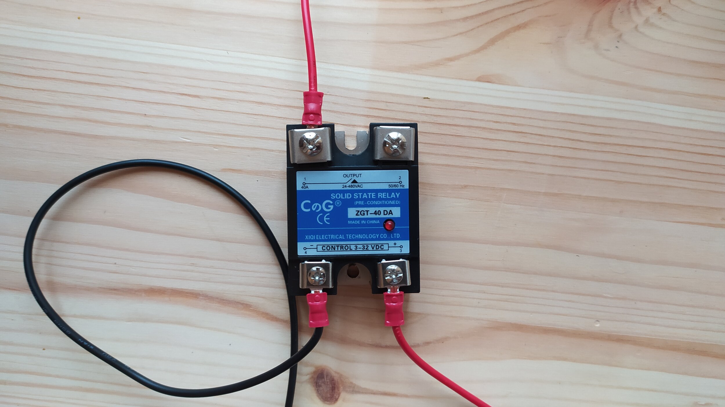
Taking one of the SSR’s remove the plastic cover. Next, take one of the 35cm Black Fork to Fork Cables and connect it to the lower-left connection point. Using the text to ensure the SSR is correctly orientated.

Step 20
Now take one of the 35cm Red Fork to Fork Cables and connect it to the lower-right connection point.
Step 21
Then take one of the 25cm Red Fork to Bare Cables and connect it to the upper-left connection point.

Step 22
Finally, take the 25cm Red Fork to Spade Cable and connect it to the upper-right connection point.

Step 23
Repeat Steps 19 to 21 for the remaining SSR. In the end you should be left with an arrangement like shown.

Step 24
Taking the SSR with all of its connection points connected, secure it to the left aluminium heatsink using 2x M4 8mm bolts.

Step 25
With the remaining SSR, and the currently vacant connection slot on the top right, connect the Fork connection that currently is connected the 5pin Wago Quick connector as shown.

Step 26
Then connect this to the right Aluminium Heatsink with the final 2x M4 8mm bolts.

Step 27
To ensure proper safety, press the plastic shields that were previously removed into place, covering the electrical contacts.

Step 28
Taking the Black and Red Cables that come out of the bottom of the SSR’s. Connect the Left SSR to the Bottom PID Controller and the Right SSR to the Top PID Controller. The Black Cable should be located on the 3rd pin from the top (on the left) (Negative) and the Red Cable to the 4th pin (Positive).
NOTE: Not all our PID controllers are the same. Some may have the NEGATIVE on the 4th pin and POSITIVE on the 3rd pin. Please make sure you switch these if your specific PID requires it.

Step 29
Take the Red Cables that are connected to the top Left of each of the SSR’s and connect them to the Wago 5pin Quick Connector.

Step 30
Next take the Red Cable that comes from the Left SSR and connect it to the rear point of the Yellow Socket as shown.

Step 31
Now take the Black 25cm Spade to Bare Cable and connect it to the closest connection point of the Yellow Socket. Then with the opposite end, connect it to the remaining empty slot of the Wago 5pin Quick Connector (the one with the 1 blue cable attached).

Step 32
Next taking the Yellow cable from the Kettle Socket, connect it to an additional Wago 5pin Quick Connector.

Step 33
Next connect the 3 Green Cables coming from the Blue and Yellow Sockets to the Wago Quick Connector.

Step 34
Finally take the 15cm Green Bare to Loop Cable, securing the loop to the M4 bolt used to mount the Kettle Socket with an M4 Lock Nut. Connect the opposite end to the Wage Quick Connector that has the Green Connectors.

Step 35
Now take one of the Thermocouple Mounts and the Thermocouple Cable. Depending on your Thermocouple cable colour either follow Steps 36 - 39 or 40 - 43
Steps 36 - 39 = Metal Encased Thermocouple
Steps 40 - 43 = Yellow Plastic Encased Thermocouple

Step 36
Bend over the ends of the Thermocouple Cable to create little loops as shown.

Step 37
Connect the two cables as shown. Making sure the orientation matches the photo.

Step 38
Now thread the Thermocouple through the slot and press into place. Repeat for the second Thermocouple.

Step 39
Now connect the Thermocouple leads to the PID’s. The Thermocouple located to the back of the box should be connected to the Top PID and the Thermocouple that is located closest to the front, should be located on the lower PID.
The Green Wire should be connected from the second from the bottom, with the Red just underneath it as shown.
Now Skip to Step 41.

Step 40
Bend over the ends of the Thermocouple Cable to create little loops as shown.

Step 41
Connect the two cables as shown. Making sure the orientation matches the photo.

Step 42
Now thread the Thermocouple through the slot and press it into place.

Step 43
Now connect the Thermocouple leads to the PID’s. The Thermocouple located to the back of the box should be connected to the Top PID and the Thermocouple that is located closest to the front, should be located on the lower PID.
The Red Wire should be connected from the second from the bottom, with the Yellow just underneath it as shown.
Repeat this step for the second PID. (Note: This image only has 1 PID, but yours will have 2.

Step 44
Finally, double check all your cables are secure, then slowly place the lid on top of the box, ensuring non of the cables are pulled, or trapped in the process.
Then secure the panel using the 4x M5 8mm Button Head Bolts, and 4x M5 washers as shown.
Then please place the electrical warning label as shown.